club car ds service manual pdf
The Club Car DS Service Manual is a comprehensive guide for maintaining and repairing Club Car DS golf carts. It provides detailed procedures, essential for owners and technicians to ensure optimal performance and longevity. The manual is available as a downloadable PDF, offering easy access to troubleshooting, maintenance schedules, and advanced repair techniques.
1.1 Overview of the Club Car DS Model
The Club Car DS is a popular electric golf cart model known for its reliability and efficiency. Produced from 1986 to 1996, it features a 36-volt electrical system, offering smooth performance and durability. Designed for both recreational and utility use, the DS model is favored for its simplicity, making it a preferred choice for golf courses and personal transportation. Its compact design and robust construction ensure long-term reliability. The Club Car DS service manual provides detailed guidance for maintaining and repairing this model, ensuring optimal performance and extending its lifespan. It covers electrical systems, mechanical components, and essential maintenance procedures.
1.2 Importance of the Service Manual
The Club Car DS service manual is an essential resource for owners and technicians, providing detailed instructions for maintenance, troubleshooting, and repairs. It ensures safety, efficiency, and optimal performance by guiding users through proper servicing procedures. The manual helps prevent costly repairs by addressing issues early and provides a reference for diagnosing and resolving common problems. By following the manual, users can maintain compliance with safety standards and extend the lifespan of their vehicle. Regular use of the manual ensures the Club Car DS operates reliably and efficiently, making it a critical tool for anyone servicing or owning the model.
1.3 Key Features of the Club Car DS
The Club Car DS is renowned for its durability and performance, featuring a robust electric or gasoline-powered engine. It offers a comfortable ride with a spacious design and customizable options. The DS model includes advanced features like the PowerDrive system, which enhances efficiency and control; Additionally, its Tranquility and IQ systems provide improved reliability and user-friendly operation. The Club Car DS also emphasizes safety with multiple braking systems and stable engineering. These features make it a popular choice for both recreational and utility purposes, ensuring a reliable and enjoyable experience for users.
Maintenance and Service Schedule
Regular maintenance is crucial for optimal performance. Schedule routine inspections, battery checks, and fluid replacements as outlined in the manual to prevent issues and extend longevity.
2.1 Routine Maintenance Checks
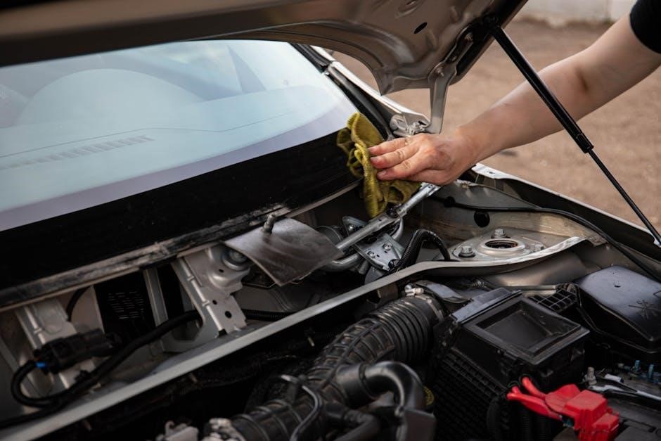
Routine maintenance checks are essential for ensuring the Club Car DS operates efficiently. Regularly inspect tire pressure, battery water levels, and brake systems. Lubricate moving parts and check for wear on components like belts and hoses. The manual recommends a detailed checklist to follow, ensuring no critical areas are overlooked. Properly maintaining these elements prevents unexpected breakdowns and extends the vehicle’s lifespan. By adhering to the suggested schedule, owners can keep their Club Car DS in optimal condition, ensuring reliability and performance over time.
2.2 Advanced Service Procedures
Advanced service procedures for the Club Car DS include detailed steps for complex repairs and upgrades. These procedures cover tasks such as replacing the PowerDrive system, upgrading electrical components, and performing throttle calibration. The manual provides in-depth instructions for diagnosing and resolving issues with the IQ System and V-Glide technology. Additionally, it outlines best practices for servicing the vehicle’s advanced features, ensuring optimal performance and reliability. By following these guidelines, technicians can confidently address sophisticated mechanical and electrical challenges, keeping the Club Car DS running at peak efficiency.
2.3 DIY Maintenance Tips
Performing routine DIY maintenance on your Club Car DS can extend its lifespan and ensure optimal performance. Regularly check tire pressure, clean battery terminals, and inspect brakes for wear. Lubricate moving parts like suspension components and steering links to reduce friction. Replace air filters and spark plugs as recommended in the manual. Check for loose connections in the wiring harness and ensure all bolts and nuts are tightened properly. These simple tasks can prevent major issues and keep your vehicle running smoothly. Always refer to the service manual for specific guidelines and safety precautions.

Troubleshooting Common Issues
Troubleshooting common issues in the Club Car DS involves identifying electrical, mechanical, or battery-related problems. Always refer to the service manual for diagnostic steps and solutions.
3.1 Electrical System Troubleshooting
Electrical system issues in the Club Car DS can often be diagnosed using the service manual. Common problems include faulty connections, blown fuses, or malfunctioning sensors. Start by checking the wiring diagrams provided in the manual to identify potential short circuits or open connections. Use a multimeter to test voltage and continuity in critical components like the battery, motor, and control board. Ensure all connections are clean and secure. Refer to the manual’s troubleshooting guide for step-by-step instructions to isolate and resolve electrical faults efficiently. Always follow safety guidelines to avoid further damage or injury.
3.2 Mechanical Component Diagnosis
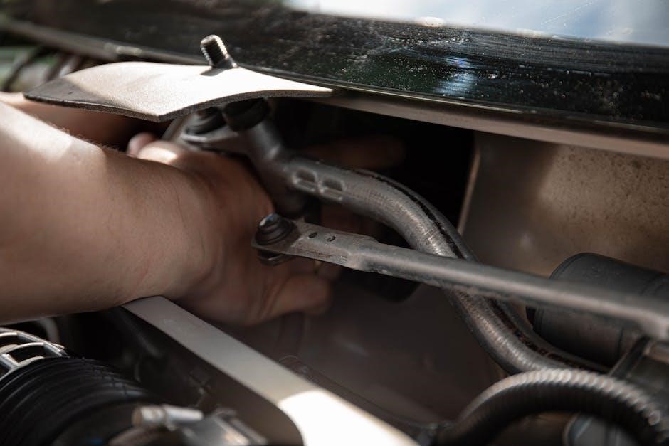
Mechanical issues in the Club Car DS often stem from wear or improper alignment. The service manual provides detailed procedures for diagnosing components like brakes, suspension, and steering. Inspect the brake system for worn pads or fluid leaks, and check suspension components for damage or looseness. Use the manual’s torque specifications to ensure proper tightening of bolts and fasteners. Lubricate moving parts regularly to prevent premature wear. For complex issues, refer to the manual’s diagnostic flowcharts to systematically identify and address mechanical faults, ensuring safe and efficient repairs.
3.3 Battery and Charging System Issues
Diagnosing battery and charging system issues in the Club Car DS is critical for reliable operation. Common problems include dead batteries, faulty chargers, or corroded connections. The service manual recommends checking voltage levels, ensuring proper electrolyte levels, and inspecting cables for damage. If the battery fails to hold charge, test each cell for internal shorts or sulfation. For charging issues, verify the charger’s output voltage matches the system requirements. Clean terminals and connectors to ensure good conductivity. Refer to the manual’s troubleshooting guide for step-by-step diagnostics and replacement procedures to restore power and functionality to your Club Car DS.

Wiring Diagrams and Schematics
Wiring diagrams provide detailed layouts of electrical systems, connections, and components. They are essential for diagnosing issues, performing repairs, and ensuring proper functionality of the Club Car DS.
4.1 Understanding the Wiring Layout
Understanding the wiring layout is crucial for effective troubleshooting and repairs. The Club Car DS service manual provides detailed diagrams and schematics to help identify components and connections. These visuals guide users through the electrical system, highlighting key circuits and their functions. By referencing these diagrams, technicians and DIY enthusiasts can trace wiring paths, locate potential issues, and ensure proper connectivity. This section is designed to simplify complex electrical systems, making it easier to diagnose and resolve problems efficiently while maintaining safety and system integrity.
4.2 Common Wiring Issues and Fixes
Common wiring issues in Club Car DS models often stem from worn connections or corrosion. The service manual outlines frequent problems like faulty solenoids, blown fuses, or damaged wires. It provides step-by-step solutions, such as replacing corroded terminals or testing circuits for continuity. DIY fixes include cleaning connectors and ensuring secure connections. For more complex issues, the manual recommends professional intervention. By addressing these problems promptly, users can prevent further damage and maintain their vehicle’s reliability and performance over time, ensuring safe and efficient operation at all times. Regular inspections are key to preventing such issues from arising.
4.3 Schematics for Advanced Repairs
The Club Car DS Service Manual includes detailed schematics to guide advanced repairs. These diagrams provide a clear visual representation of electrical and mechanical systems, aiding in complex troubleshooting. Technicians can use these schematics to identify faulty components, trace wiring paths, and understand system interactions. The manual also offers step-by-step instructions for interpreting the diagrams, ensuring accurate diagnoses and repairs. Whether addressing electrical faults or mechanical failures, the schematics serve as an invaluable resource for maintaining and restoring the Club Car DS to optimal functionality and performance over time.
Model-Specific Information
This section provides detailed specifications and maintenance guidelines for various Club Car DS models, including the 1995-1996, 2001-2003 upgrades, and the PowerDrive system.
5.1 1995-1996 Club Car DS Models
The 1995-1996 Club Car DS models are popular for their durability and performance. This section of the manual provides specific maintenance and repair guidelines for these models, including detailed procedures for electrical and mechanical systems. It also covers unique features of these earlier models, such as the original PowerDrive system. Supplementary information includes part numbers and compatibility, ensuring accurate servicing. The manual emphasizes the importance of following recommended procedures to maintain vehicle efficiency and longevity. Owners are advised to consult this section for model-specific instructions before attempting any repairs or upgrades.
5.2 2001-2003 Club Car DS Upgrades
The 2001-2003 Club Car DS models introduced significant upgrades, enhancing performance and durability. This section details these improvements, including the advanced PowerDrive system and IQ System upgrades. The manual provides guidance on integrating these upgrades and troubleshooting specific issues related to them. It also covers compatibility with earlier models and essential maintenance routines to optimize the new features. Owners and technicians can refer to this section for detailed instructions on upgrading and servicing these models effectively, ensuring continued reliability and efficiency. Proper servicing of these upgrades is crucial for maintaining the vehicle’s overall performance.
5.3 Club Car DS PowerDrive System
The Club Car DS PowerDrive system represents a significant advancement in electric vehicle technology, offering enhanced torque and efficiency. This section of the service manual provides in-depth information on the PowerDrive system’s components, installation, and maintenance. It covers troubleshooting common issues and outlines the procedures for upgrading older models to the PowerDrive system. Detailed diagrams and step-by-step instructions ensure that technicians and owners can service and optimize the system effectively. Proper care of the PowerDrive system is essential to maintain the vehicle’s performance and extend its lifespan.
Safety Guidelines and Precautions
Always wear protective gear and use proper tools when servicing the Club Car DS. Follow safety protocols to avoid injuries and ensure proper repairs. Adhere to guidelines.
6.1 Safety Tips for Servicing the Vehicle
Always disconnect the battery before starting any service to prevent electrical shocks or unexpected startups. Wear protective gear, including gloves and safety glasses. Ensure the vehicle is on a level surface and apply brakes securely. Use jack stands for lifting, never rely solely on jacks. Follow the manual’s guidelines for safe repair practices. Keep loose clothing and long hair tied back to avoid accidents. Be cautious of hot components and sharp edges. Ensure proper ventilation when working with batteries or electrical systems. Familiarize yourself with emergency procedures before beginning any task.
6.2 Protective Gear and Tools
When servicing your Club Car DS, always wear protective gear, including gloves, safety glasses, and a face mask. Use a well-lit workspace and ensure the vehicle is on a level surface. Keep tools organized to avoid accidents. Essential tools include a socket set, wrenches, and pliers. For electrical work, use insulated tools to prevent shocks. Refer to the manual for specific tool recommendations. Proper equipment ensures safe and effective servicing, protecting both you and your vehicle from potential damage.
6.3 Emergency Procedures
In case of an emergency while servicing your Club Car DS, disconnect the battery and ensure the vehicle is stable. For fire, use a fire extinguisher rated for electrical fires. If injured, seek medical help immediately. Spills of hazardous materials should be contained and cleaned according to regulations. Keep a first aid kit nearby and have emergency contact numbers accessible. Always follow the manual’s guidelines to prevent accidents and respond effectively in emergencies, ensuring safety for yourself and others.
Environmental Compliance and Best Practices
Adhering to environmental regulations is crucial. Properly dispose of hazardous materials like batteries and fluids. Follow energy-efficient practices and eco-friendly maintenance procedures to minimize the vehicle’s ecological impact.
7.1 Proper Disposal of Hazardous Materials
Proper disposal of hazardous materials is essential to protect the environment. Dispose of batteries, fluids, and other harmful substances at designated recycling facilities. Avoid draining or disposing of these materials improperly, as they can contaminate soil and water. Refer to the Club Car DS service manual for specific guidelines on handling and recycling hazardous components. Always follow local regulations and eco-friendly practices to ensure safe disposal. This helps minimize environmental impact and promotes sustainability.
7.2 Energy Efficiency and Eco-Friendly Practices
Energy efficiency and eco-friendly practices are crucial for maintaining the Club Car DS. Regular battery maintenance ensures optimal performance and longevity, reducing energy waste. Use energy-efficient chargers and avoid overcharging to minimize power consumption. Eco-friendly practices include proper disposal of hazardous materials and recycling of old parts. Adhere to local environmental regulations to reduce your ecological footprint. By following these guidelines, you contribute to sustainability while keeping your Club Car DS running efficiently. These practices not only benefit the environment but also extend the lifespan of your vehicle.
7.3 Compliance with Local Regulations
Compliance with local regulations is vital when servicing the Club Car DS. Familiarize yourself with regional environmental and safety laws to ensure adherence. Proper disposal of hazardous materials, such as batteries and fluids, must follow local guidelines. Additionally, noise and emission standards may apply, especially in residential areas. Always check for any specific permits or certifications required for maintenance and repair. By adhering to these regulations, you avoid legal issues and contribute to community safety. Stay informed about updates to local laws to maintain full compliance throughout your Club Car DS ownership.
Accessing the Service Manual Online
The Club Car DS service manual is easily downloadable as a PDF from the official Club Car website or authorized distributors, ensuring convenient access for all users.
8.1 Downloading the PDF Version
The Club Car DS service manual PDF can be downloaded directly from the official Club Car website or authorized distributors. Users can access the manual by navigating to the support or resources section. Some websites may require registration or signing in to download the PDF. Ensure compatibility with your device, as the manual is optimized for various platforms. The PDF format allows for easy searching and navigation, making it convenient to find specific repair or maintenance procedures quickly. Always verify the source to ensure you are downloading the correct and updated version of the manual for your Club Car DS model.
8.2 Navigating the Digital Manual
Navigating the Club Car DS service manual PDF is straightforward, with features like bookmarks and a table of contents for easy access to specific sections. Use the search function to quickly locate topics like maintenance schedules or troubleshooting guides. The manual is organized by categories, such as electrical systems, mechanical components, and battery care, ensuring users can find information efficiently. Hyperlinks within the document allow for seamless navigation between related sections. Additionally, the PDF is zoomable, making it easy to read detailed diagrams or small text on any device, from smartphones to desktops.
8.3 Updates and Revisions
Regular updates and revisions to the Club Car DS service manual PDF ensure it remains accurate and relevant. These updates often include new diagnostic procedures, enhanced repair techniques, and compliance with the latest industry standards. Users are encouraged to check Club Car’s official website for the most recent version. Notifications about updates may also be available through email subscriptions or within the manual’s digital platform. Always use the latest version to access the most current information for optimal servicing and maintenance of your Club Car DS vehicle.
Additional Resources and Support
Explore official Club Car resources, including their website and customer service; Find community support through forums and authorized service centers. Access user manuals and service supplements online.
9.1 Contacting Club Car Customer Service
Club Car customer service is readily available to assist with inquiries, repairs, and manual downloads. Visit their official website or call their support hotline for direct assistance. For specific requests, email their customer care team, providing your vehicle’s serial number and details about your needs. They can help with troubleshooting, service manual downloads, and ordering printed copies. Additionally, their team can guide you to authorized dealers for parts and accessories, ensuring genuine products for your Club Car DS. Their support extends to technical questions and warranty inquiries, making them a reliable resource for all your servicing needs.
9.2 Online Communities and Forums
Online communities and forums dedicated to Club Car DS owners and enthusiasts provide valuable resources and support. Platforms like Golf Cart Forum and Club Car enthusiast groups offer a space to discuss maintenance tips, troubleshooting, and DIY projects. Members share experiences, repair guides, and modifications, helping users optimize their vehicles. These forums also host discussions on service manuals, wiring diagrams, and accessory installations. Engaging with these communities can provide additional insights and solutions beyond the official manual, fostering a collaborative environment for Club Car DS owners to learn and grow together.
9.3 Authorized Service Centers
Authorized Club Car service centers provide professional maintenance and repairs for Club Car DS models. These centers employ certified technicians who follow the guidelines outlined in the Club Car DS service manual. They use genuine parts and ensure compliance with safety and performance standards. For complex issues or advanced repairs, visiting an authorized service center is highly recommended. You can locate these centers through Club Car’s official website or contact their customer support. Regular servicing at these centers helps maintain your vehicle’s warranty and ensures optimal performance. Always verify the center’s authorization to guarantee reliable and high-quality service.
The Club Car DS Service Manual is a valuable resource for maintaining and repairing your vehicle. Regular servicing ensures optimal performance and longevity, while proper repairs guarantee safety and efficiency. Always consult authorized service centers for complex issues to maintain compliance and warranty validity. Follow the manual’s guidelines to keep your Club Car DS in prime condition.
10.1 Summary of Key Points
The Club Car DS Service Manual provides comprehensive guidance for maintaining and repairing your vehicle. It covers essential topics like routine maintenance, troubleshooting, wiring diagrams, and safety protocols. The manual also includes model-specific information, environmental compliance, and resources for accessing support. By following the manual, users can ensure optimal performance, longevity, and safety of their Club Car DS. Regular servicing and adherence to guidelines are crucial for maintaining warranty validity and operational efficiency. This resource is invaluable for both owners and technicians, offering detailed insights to keep your Club Car DS in excellent condition.
10.2 Final Tips for Users
Always refer to the Club Car DS Service Manual before performing repairs or maintenance. Ensure all safety precautions are followed to avoid accidents. Regularly inspect and replace worn components to maintain performance. Use genuine Club Car parts for reliability and warranty compliance. Keep the manual handy for quick reference during servicing. For complex issues, consult authorized service centers or experienced technicians. Stay updated with the latest manual revisions for accurate guidance. Proper maintenance ensures longevity, safety, and optimal functionality of your Club Car DS. Adhere to environmental guidelines when handling hazardous materials. Consistent upkeep guarantees a smooth and trouble-free experience.
10.3 Importance of Regular Servicing
Regular servicing is crucial for maintaining the performance, efficiency, and longevity of your Club Car DS. It ensures all components function optimally, preventing unexpected breakdowns and costly repairs. Routine checks, as outlined in the service manual, help identify potential issues early, enhancing safety and reliability. Proper maintenance also preserves the vehicle’s value and ensures compliance with environmental standards. By following the recommended schedules and guidelines, users can extend the lifespan of their Club Car DS, ensuring it operates efficiently for years to come. Consistent upkeep is key to a smooth and trouble-free ownership experience.