delta controls thermostat user manual
Delta Controls offers advanced building automation solutions, including thermostats like the eZNTW, enhancing energy efficiency and comfort.
These systems integrate seamlessly with Freebox Delta and BACnet networks.
What are Delta Controls Thermostats?
Delta Controls Thermostats represent a sophisticated approach to building climate management, moving beyond simple temperature regulation. They are intelligent devices designed for precise heating and cooling control within commercial and residential environments. These thermostats, particularly the eZNTW model, leverage BACnet communication protocols for seamless integration into larger building automation systems.
Unlike conventional thermostats, Delta Controls units offer advanced features like scheduling, remote access (potentially via Freebox Delta integration), and detailed energy reporting. They are engineered to optimize energy usage, reduce operational costs, and enhance occupant comfort through precise temperature maintenance and customizable settings;
Key Features and Benefits
Delta Controls Thermostats boast several key advantages. BACnet compatibility ensures interoperability with existing building management systems, streamlining integration. The eZNTW model offers advanced scheduling capabilities, optimizing energy consumption based on occupancy patterns. Potential Freebox Delta integration promises remote access and control, enhancing convenience.
Benefits include reduced energy costs, improved occupant comfort, and detailed energy reporting for informed decision-making. Features like Sigma-Delta modulation contribute to precise temperature control. These thermostats provide a robust and scalable solution for modern building automation needs, offering long-term value.
Understanding the eZNTW Model
The eZNTW is a sophisticated BACnet thermostat from Delta Controls, known for its advanced features and compatibility with enteliZONE systems for optimal control.
eZNTW: An Advanced BACnet Thermostat
The eZNTW thermostat represents a significant advancement in Delta Controls’ offerings, functioning as a powerful BACnet Master device. It’s designed for precise temperature regulation within building automation systems, offering robust communication capabilities and extensive configuration options. This model supports various control algorithms, including PID control, ensuring optimal comfort and energy savings. Its advanced features allow for detailed scheduling, remote access, and integration with broader building management platforms. The thermostat’s design prioritizes user-friendliness alongside its technical sophistication, making it suitable for diverse applications and skill levels.
enteliZONE Compatibility
The eZNTW seamlessly integrates with Delta Controls’ enteliZONE system, a comprehensive zoning solution for precise HVAC control. This compatibility allows for individualized temperature management across multiple zones within a building, maximizing comfort and minimizing energy waste. enteliZONE enables centralized control and monitoring of all thermostats, simplifying building management. Users can create customized schedules and setpoints for each zone, optimizing performance based on occupancy and usage patterns. This synergy delivers a highly efficient and responsive climate control experience.
Technical Specifications of eZNTW
The eZNTW is an advanced BACnet thermostat featuring a high-resolution display and intuitive interface. It supports various heating and cooling control types, including conventional, heat pump, and fan coil systems. Power supply operates on 24VAC, with a current draw of less than 500mA. eZNTW boasts a temperature sensing accuracy of ±0.5°C and a communication speed of 9600/19200/38400/76800 bps. Its compact design ensures easy installation, while robust construction guarantees long-term reliability within diverse environments.

Installation Guide
Proper installation requires careful wiring and mounting, ensuring compatibility with your HVAC system. Refer to detailed diagrams for BACnet integration and safe power-up procedures.
Wiring Diagrams for Different Systems
Delta Controls thermostats accommodate various HVAC configurations. Detailed wiring diagrams are crucial for correct installation, ensuring optimal performance and preventing damage. These diagrams illustrate connections for conventional systems, heat pump setups, and multi-stage heating/cooling.
Specifically, diagrams detail wiring for 24VAC power, fan control, heating, cooling, and common connections. BACnet communication wiring is also clearly shown, including data positive, data negative, and shield connections. Always disconnect power before wiring and verify compatibility with your existing system. Incorrect wiring can void the warranty and cause system malfunction.
Mounting the Thermostat
Delta Controls thermostats require secure mounting for accurate temperature sensing and reliable operation. Select a location away from direct sunlight, drafts, and heat-generating appliances. Use the provided mounting plate as a template to mark screw holes on the wall.
Ensure the surface is level before attaching the plate with appropriate screws. Carefully connect the wiring before snapping the thermostat onto the mounting plate. Verify a snug fit and proper alignment. Avoid excessive force during mounting to prevent damage to the unit or wall surface.
Initial Power-Up and Configuration
Upon initial power-up, the Delta Controls thermostat will initiate a self-test sequence. Allow this process to complete before proceeding. Access the configuration menu using the designated buttons on the user interface. Set the correct date and time, ensuring accuracy for scheduling functions.
Configure network settings, including BACnet communication parameters, if connecting to a building automation system. Define the system type (heating, cooling, or heat pump) and configure temperature scales (Celsius or Fahrenheit). Save all settings before exiting the configuration mode.
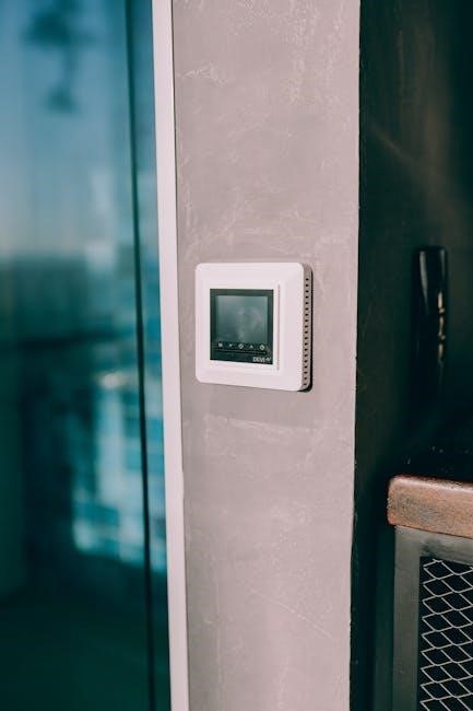
User Interface Overview
Delta Controls thermostats feature intuitive displays with symbols indicating system status. Navigation is menu-driven, allowing easy adjustment of temperature and scheduling preferences.
Display Symbols and Indicators
Delta Controls thermostats utilize a comprehensive system of display symbols to communicate vital information at a glance. A flame icon signifies active heating, while a snowflake indicates cooling is engaged. Fan symbols denote fan operation modes – auto, on, or circulate.
A Wi-Fi symbol confirms network connectivity, crucial for remote access and building automation system integration. Error codes, displayed as alphanumeric sequences, signal potential issues requiring attention. Battery indicators, where applicable, show remaining power levels. Understanding these symbols empowers users to quickly assess system status and troubleshoot minor concerns without extensive manual review.
Navigating the Menu System
Delta Controls thermostats feature an intuitive menu system accessed via dedicated buttons – typically ‘Menu’, ‘Up’, ‘Down’, and ‘Enter’ or ‘Select’. Pressing ‘Menu’ initiates the main menu, presenting options like ‘Schedule’, ‘Settings’, ‘Information’, and ‘Network’.
Use ‘Up’ and ‘Down’ to scroll through options, and ‘Enter’ to select. Submenus are navigated similarly. The ‘Back’ or ‘Escape’ button returns to the previous screen. Familiarizing yourself with this structure allows for efficient customization of temperature settings, scheduling preferences, and advanced configurations, optimizing comfort and energy savings.
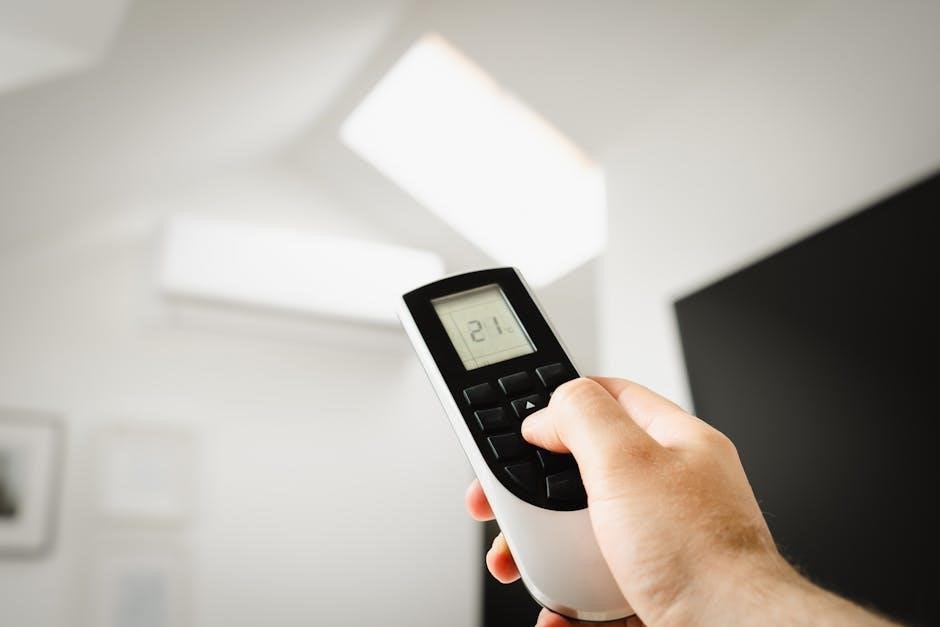
Adjusting Temperature Settings
Delta Controls thermostats allow precise temperature adjustments through the menu system or directly via dedicated buttons, if equipped. Within the ‘Temperature’ or ‘Setpoint’ menu, use the ‘Up’ and ‘Down’ arrows to increase or decrease the desired temperature.
The display clearly shows the current setpoint and the actual room temperature. Some models offer ‘Hold’ functionality, maintaining a specific temperature indefinitely, overriding scheduled programs. Remember to confirm changes by pressing ‘Enter’ or ‘Select’ to ensure the new setting is applied.

Programming Schedules
Delta Controls thermostats enable customized heating/cooling schedules for optimal comfort and energy savings. Users can define time-based temperature setpoints easily.
Creating Custom Schedules
Delta Controls thermostats empower users to design personalized comfort profiles through custom scheduling. Access the programming menu via the thermostat’s interface, then define unique setpoints for different times and days. You can establish separate schedules for weekdays versus weekends, or even create individual schedules for each day of the week.
Consider occupancy patterns when setting temperatures – lower settings during unoccupied hours maximize energy efficiency. The system supports multiple schedule periods per day, allowing for granular control. Save your customized schedule to activate it, ensuring consistent and automated temperature management.
Setting Time and Date
Accurate time and date settings are crucial for proper schedule operation within your Delta Controls thermostat. Navigate to the settings menu, typically accessible through the thermostat’s display interface. Locate the “Time & Date” option and select it. Use the navigation buttons to adjust the current year, month, day, hour, and minute.
Ensure the correct time zone is selected for your location. Saving these settings synchronizes the thermostat’s internal clock, enabling automated scheduling and accurate time-stamping of events. Verify the settings after saving to confirm accuracy.
Holiday and Vacation Modes
Delta Controls thermostats offer convenient Holiday and Vacation modes for energy savings during extended absences. These modes override programmed schedules, maintaining a pre-defined setback temperature. Access these options through the thermostat’s menu system, typically under “Scheduling” or “System Settings.”
Specify the start and end dates for your absence. Choose a comfortable, yet energy-efficient, setback temperature. Upon your return, the thermostat automatically resumes the regular programmed schedule, ensuring optimal comfort and efficiency.

Network Connectivity
Delta Controls thermostats utilize BACnet communication protocols for seamless integration into building automation systems, enabling remote monitoring and control capabilities.
BACnet Communication Protocols
Delta Controls thermostats leverage the BACnet (Building Automation and Control Networks) protocol, a widely adopted standard for building automation systems. This ensures interoperability with a diverse range of devices and controllers. The eZNTW model specifically supports various BACnet services, including reading and writing object properties, alarming, and trending.
Successful BACnet communication requires proper network configuration, including IP addressing, subnet masks, and gateway settings. Understanding BACnet object types and their associated properties is crucial for effective integration. Troubleshooting network issues often involves verifying device discovery, checking communication logs, and confirming network connectivity.
Connecting to a Building Automation System
Integrating Delta Controls thermostats into a Building Automation System (BAS) unlocks advanced control and monitoring capabilities. Utilizing BACnet, the eZNTW seamlessly communicates with central controllers, enabling remote temperature adjustments, scheduling, and energy management. Proper network configuration is paramount, ensuring the thermostat is discoverable and accessible within the BAS.
Configuration typically involves mapping thermostat points (temperature, setpoint, status) to corresponding BAS variables. Secure communication protocols and authentication methods should be implemented to protect system integrity. Successful integration enhances building efficiency and provides valuable data for performance analysis.
Troubleshooting Network Issues
Network connectivity problems with Delta Controls thermostats often stem from BACnet communication failures. Verify physical layer connections – cabling, termination resistors – and confirm the thermostat’s IP address is correctly configured and doesn’t conflict with other devices. Utilize network diagnostic tools to ping the thermostat and check for packet loss.
If issues persist, examine the BAS configuration for incorrect mappings or communication settings. Firewall restrictions or network segmentation can also impede communication. Consulting the Delta Controls documentation and support resources is crucial for resolving complex network challenges.
Advanced Settings
Delta Controls thermostats offer customizable PID control, filter cycling, and sensor calibration options for optimized performance and tailored building automation solutions.
PID Control Parameters
Delta Controls thermostats utilize Proportional-Integral-Derivative (PID) control for precise temperature regulation. Adjusting these parameters – Proportional Gain (Kp), Integral Time (Ti), and Derivative Gain (Td) – allows fine-tuning of system responsiveness and stability.
Higher Kp values increase responsiveness but can cause oscillation. Decreasing Ti shortens the integral action, speeding up correction, while increasing Td anticipates future errors. Careful calibration, considering building characteristics and HVAC system dynamics, is crucial for optimal performance and energy efficiency. Incorrect settings can lead to temperature fluctuations or instability.
Filter Cycling and Maintenance Reminders
Delta Controls thermostats can be programmed to cycle fan operation, even during heating or cooling inactivity, to improve indoor air quality by filtering air continuously. This feature minimizes dust and allergen buildup.
The system also provides configurable maintenance reminders for filter replacement, ensuring optimal HVAC system performance and longevity. Users can set reminder intervals based on filter type and usage. Ignoring these reminders can reduce efficiency and potentially damage equipment, increasing energy costs and repair needs.
Sensor Calibration
Delta Controls thermostats utilize precise temperature sensors, but periodic calibration may be necessary to maintain accuracy. The user manual details procedures for verifying sensor readings against a known standard.
Calibration adjustments are accessible through the advanced settings menu, allowing technicians to fine-tune temperature measurements. Proper calibration ensures accurate temperature control, optimizing comfort and energy efficiency. Incorrectly calibrated sensors can lead to system inefficiencies and inaccurate temperature reporting within the BACnet network.
Troubleshooting Common Issues
Delta Controls thermostats may experience power failures, incorrect readings, or communication errors. Consult the user manual for diagnostic steps and solutions.
Thermostat Not Powering On
If your Delta Controls thermostat fails to power on, begin by verifying the power source. Ensure the wiring connections are secure and correspond correctly to the system’s wiring diagram. Check the circuit breaker or fuse associated with the thermostat’s power supply; a tripped breaker or blown fuse will prevent operation.
Confirm that the thermostat is receiving the appropriate voltage. If using batteries (if applicable), replace them with fresh ones. Inspect the wiring for any damage or shorts. If the issue persists, consult a qualified HVAC technician or Delta Controls technical support for further assistance.
Incorrect Temperature Readings
If your Delta Controls thermostat displays inaccurate temperature readings, first check for obstructions near the sensor. Ensure furniture, curtains, or other objects aren’t affecting airflow or directly exposing the sensor to sunlight or heat sources. Verify the thermostat’s location isn’t in a drafty area.
Attempt a sensor calibration within the advanced settings menu. If the problem continues, consider potential interference from nearby electronic devices. Contact Delta Controls support if calibration doesn’t resolve the issue, as a faulty sensor may require replacement.
Communication Errors
Experiencing communication errors with your Delta Controls thermostat? First, verify the physical network connections – ensure all wiring is secure and correct, particularly regarding BACnet protocols. Check the building automation system (BAS) for network conflicts or IP address issues. Confirm the thermostat’s network settings match the BAS configuration.
Restart both the thermostat and the BAS. If problems persist, consult the network troubleshooting section of the manual or contact Delta Controls technical support for assistance with network diagnostics.

Maintenance and Care
Regular cleaning with a soft cloth ensures optimal performance. Check for necessary software updates via the Delta Controls website to maintain functionality.
Cleaning the Thermostat
Maintaining a clean thermostat is crucial for accurate readings and longevity. Before cleaning, always ensure the system is powered off or set to the “off” position to prevent accidental adjustments or electrical hazards. Use a soft, dry cloth to gently wipe the thermostat’s surface, removing dust and debris.
Avoid using abrasive cleaners, solvents, or excessive moisture, as these can damage the display or internal components. For stubborn marks, lightly dampen the cloth with water, ensuring it’s wrung out thoroughly. Never spray liquids directly onto the thermostat. Regular cleaning, approximately every three months, will help keep your Delta Controls thermostat functioning optimally.
Battery Replacement (if applicable)
Some Delta Controls thermostats utilize batteries as a backup power source or for specific functionalities. If your model requires batteries, a low battery indicator will appear on the display. To replace, carefully open the battery compartment, typically located on the back or side of the unit.
Note the battery type required (usually AA or AAA) and replace with fresh batteries of the same type. Ensure correct polarity (+ and -) during installation. After replacement, the thermostat should automatically resume normal operation. Dispose of old batteries responsibly, following local regulations.
Software Updates
Delta Controls regularly releases software updates to improve thermostat performance, add features, and enhance security. These updates are typically delivered via the connected BACnet network or through a direct connection to a computer. Check the Delta Controls website for the latest available updates and instructions.
Before updating, it’s crucial to back up your current configuration settings. Follow the on-screen prompts carefully during the update process, and avoid interrupting power to the thermostat. A successful update will optimize your system and ensure compatibility.
Delta Controls and Freebox Delta Integration (Potential)
Delta Controls thermostats may integrate with Freebox Delta, offering remote access and control via home automation systems, enhancing convenience and efficiency.
Exploring Compatibility with Freebox Delta
Investigating the potential synergy between Delta Controls thermostats and the Freebox Delta presents exciting possibilities for enhanced home automation. Current discussions suggest users are seeking ways to leverage the Freebox Delta’s capabilities, like its server and network features, to control and monitor their heating and cooling systems more effectively.
Specifically, integrating Delta Controls thermostats could allow for remote temperature adjustments, scheduling, and energy usage monitoring directly through the Freebox Delta interface. However, compatibility relies on establishing seamless communication protocols, potentially utilizing BACnet or other integration methods. Further research and development are needed to fully unlock this potential.
Potential for Remote Access and Control
Integrating Delta Controls thermostats with a system like Freebox Delta unlocks significant remote access and control capabilities. Users could adjust temperature settings, create custom schedules, and monitor energy consumption from anywhere with an internet connection. This is particularly valuable for vacation homes or ensuring comfort upon arrival.
The Freebox Delta’s network connectivity and potential for custom domain names (.freeboxos.fr) could facilitate secure remote access. However, successful implementation requires robust network security and a user-friendly interface for managing thermostat settings remotely, potentially through a dedicated mobile application or web portal.
Considerations for Home Automation Systems
Integrating Delta Controls thermostats into broader home automation ecosystems demands careful consideration. Compatibility with protocols beyond BACnet, like Zigbee or Z-Wave, may require additional gateways or bridges. Ensuring seamless interaction with other smart home devices – lighting, security systems, and voice assistants – is crucial for a unified experience.
The Freebox Delta, with its processing power and storage (DDR4, 2To+), could potentially act as a central hub. However, stability and reliability are paramount; reported issues with the Freebox Ultra necessitate thorough testing before relying on it for critical climate control functions.
Sigma-Delta Modulation in Thermostat Operation
Sigma-Delta DACs and ADCs enhance precision in Delta Controls thermostats by converting analog signals with high resolution and reduced noise, improving accuracy.
How Sigma-Delta DACs and ADCs are Used
Delta Controls thermostats utilize Sigma-Delta Analog-to-Digital Converters (ADCs) to precisely measure temperature from sensors, converting analog readings into digital values for processing. Conversely, Sigma-Delta Digital-to-Analog Converters (DACs) translate digital control signals into analog outputs, accurately adjusting heating or cooling actuators.
These converters employ oversampling and noise shaping techniques, pushing quantization noise to higher frequencies where it’s easily filtered. This results in higher resolution and improved signal-to-noise ratio, crucial for maintaining stable and accurate temperature control within building automation systems. The modulation process ensures reliable performance and energy efficiency.
Benefits of Sigma-Delta Technology
Sigma-Delta technology within Delta Controls thermostats delivers exceptional linearity and accuracy in temperature sensing and control. Its inherent noise shaping capabilities minimize quantization errors, resulting in precise and stable heating/cooling. This leads to improved energy efficiency and occupant comfort.
Furthermore, the simplicity of the modulator design allows for easier calibration and reduces the impact of component variations. The technology’s robustness ensures reliable operation over a wide temperature range, contributing to the longevity and performance of the thermostat system.

Delta-V and Thermostat Control
Delta-V, representing temperature differences, is crucial for efficient heating and cooling systems managed by Delta Controls thermostats, optimizing system performance.
Relationship to Heating and Cooling Systems
Delta Controls thermostats act as intelligent interfaces within broader HVAC systems. They receive temperature data, compare it to setpoints, and modulate heating or cooling outputs accordingly. This precise control, often utilizing PID control, ensures consistent comfort and minimizes energy waste.
The thermostats communicate with boilers, chillers, and air handling units, adjusting dampers and valves to maintain desired conditions. Integration with systems like Delta-V allows for optimized performance, considering factors like building load and outdoor temperature. Proper configuration is key to maximizing efficiency and responsiveness within the entire HVAC infrastructure.
Impact on System Efficiency
Delta Controls thermostats significantly boost HVAC system efficiency through precise temperature regulation and intelligent scheduling. Features like filter cycling reminders and optimized PID control parameters minimize energy consumption. Network connectivity via BACnet enables centralized monitoring and adjustments, further refining performance.
By preventing temperature swings and adapting to occupancy patterns, these thermostats reduce unnecessary heating or cooling. Integration with building automation systems allows for holistic energy management, optimizing overall building performance and lowering operational costs. This contributes to a more sustainable and cost-effective environment.
Resources and Support
Delta Controls provides extensive online documentation and a dedicated technical support team. Access manuals, FAQs, and contact information via their official website for assistance.
Delta Controls Website and Documentation
Delta Controls’ official website serves as a central hub for comprehensive resources related to their thermostats, including detailed user manuals, specification sheets, and application notes. Users can navigate to the support section to find downloadable documents specific to the eZNTW model and other enteliZONE compatible devices.
The documentation covers installation procedures, wiring diagrams, network configuration, troubleshooting guides, and advanced settings explanations. Furthermore, the website features a knowledge base with frequently asked questions and helpful articles addressing common issues. Registered users often gain access to exclusive content and software updates, ensuring optimal thermostat performance and integration within building automation systems.
Contacting Technical Support
Delta Controls provides multiple avenues for accessing technical support regarding their thermostats and related systems. Users can initiate contact through the company’s official website, utilizing a dedicated support request form for detailed inquiries. Alternatively, direct phone support is available during standard business hours, connecting users with knowledgeable technicians.
Email support offers another convenient option, allowing for asynchronous communication and detailed issue descriptions. When contacting support, having the thermostat model number, serial number, and a clear description of the problem is crucial for efficient resolution. Accessing the online documentation beforehand can also expedite the troubleshooting process.